Vintage Radio
The Radio - Hammarlund-Roberts Junior circa 1933 - Restoration
The Hammarlund-Roberts Junior is a Tuned Radio Frequency (TRF) receiver from around 1933. A tuned radio frequency receiver is a type of radio receiver that is composed of one or more tuned radio frequency (RF) amplifier stages followed by a detector (demodulator) circuit to extract the audio signal and usually an audio frequency amplifier. This type of receiver was popular in the 1920s. Early radios could be tedious to operate because when tuning in a station each stage had to be individually adjusted to the station's frequency.
The radio comprises 4 stages; one RF amplifier, one (Grid-leak) Detector Amplifier, and two audio amplifiers which are coupled together with interstage audio transformers.
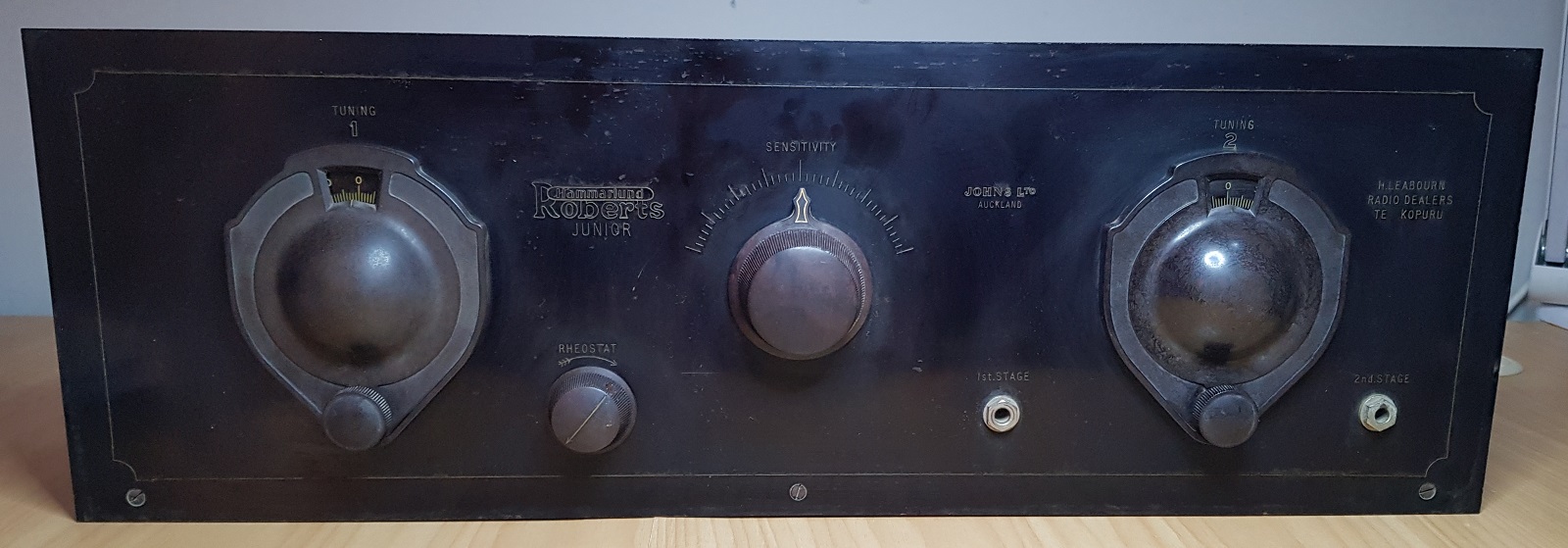
Hammarlund-Roberts Junior was available as a kit, but Johns Ltd. assembled it completely and made at least one modification by using European 01A Triode and socket types instead of original A409/B406 US Tubes. This radio is signed (engraved) Johns Ltd. Auckland and H Leabourn Radio Dealers Te Kopuru .
Source - Radiomuseum/The Golden Age of Radio in the Home 1986
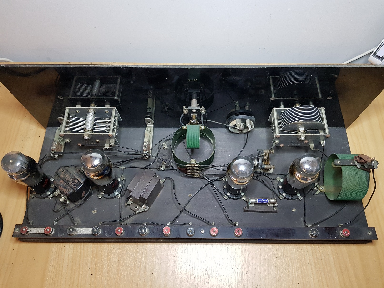
- Number of Tubes 4
- Valves / Tubes 01A, 01A, 01A, 01A (European 01A triode and socket types) PDF Article - The Grand Old 01A
- Main principle TRF with regeneration
- Tuned circuits 2 AM circuit(s)
- Wave bands Broadcast only (MW).
- Power type and voltage Storage and/or dry batteries
- Loudspeaker headphones or amp.
- Material Wooden case
- Shape Table model, Box with Lid
- Dimensions (WHD) 680 x 240 x 300 mm / 26.8 x 9.4 x 11.8 inch
- Volume control Volume control via the filament rheostat.
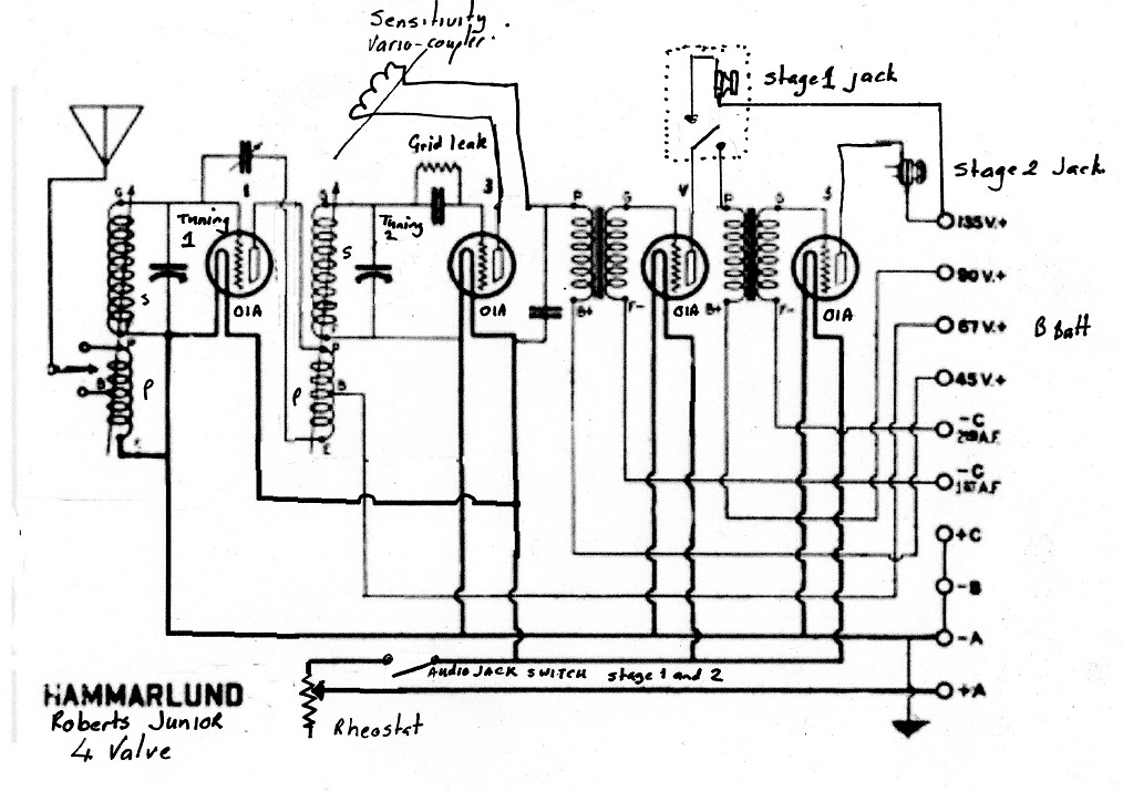
The 4 value schematic below is a modification of the 5 value schematic taken from - Radio Age Article in February 1927 " Building the Hammarlund-Roberts Part 1 by Leslie G. Biles" - Link is to PDF of this magazine - article on page 7.
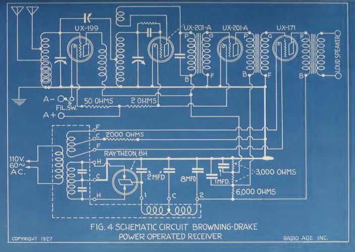
Similar circuit from 1927 with PSU (source Radio Age February 1927 page 33 )
Original 5 Valve circuit for Hammarlund-Roberts
RF Stage
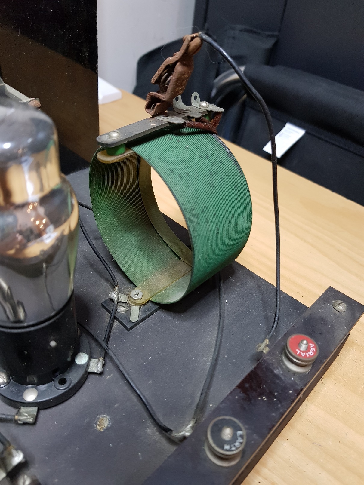
The RF stage comprises a tapped primary coil for tuning and matching the recieved signal to the RF amplifier
(Grid-leak) Detector Amplifier
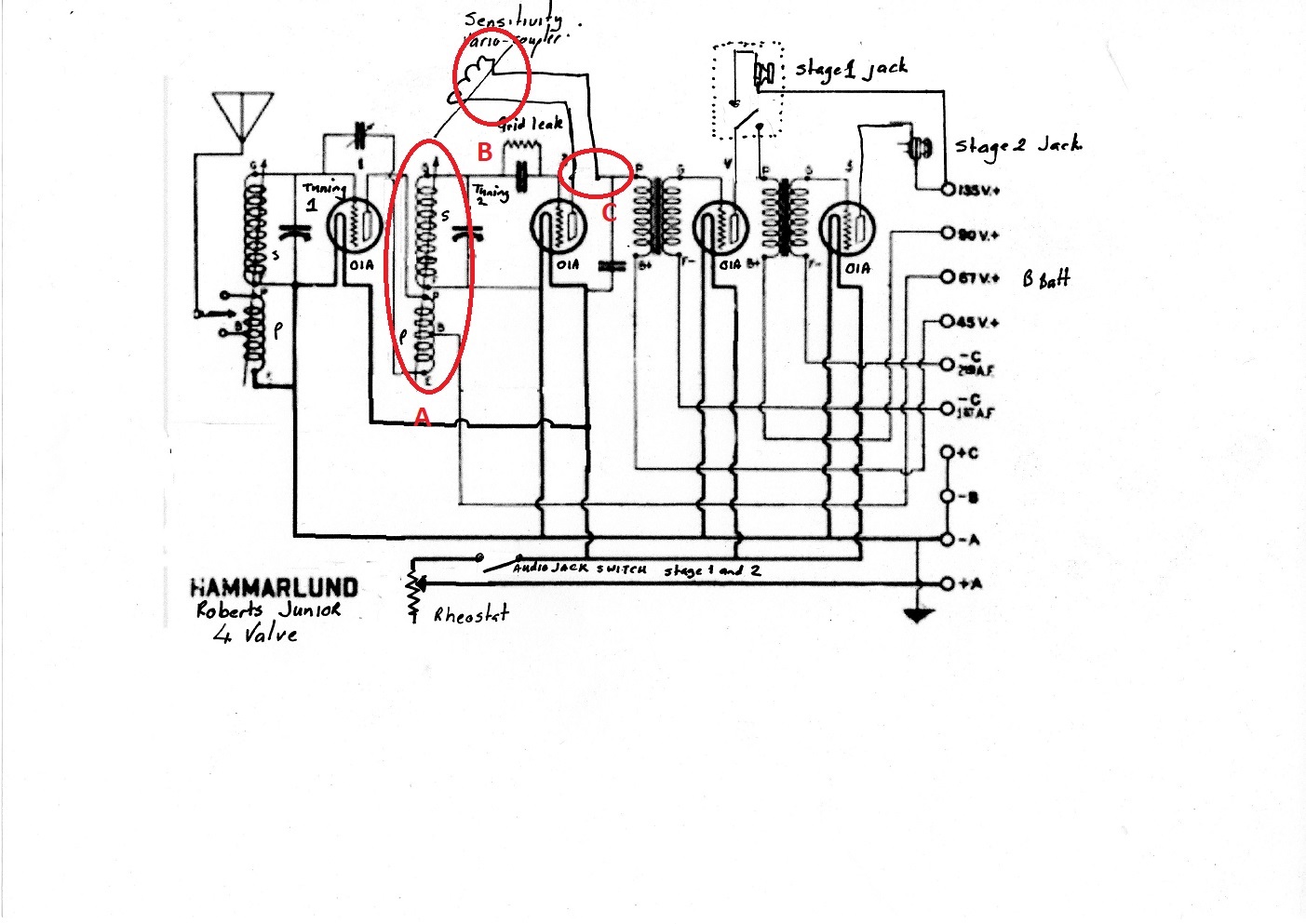
The RF / Detector stage de-modulates the RF and provides regeneration back to the RF amplifier stage. It comprises a tuned circuit, grid leak detector and vario-coupler.
coils performs 3 functions
- impeadence matching and mutual inductance between the output of the 1st RF stage and input to the second RF/Detector stage (A)
- The regenerative winding or "tickler coil" (B)
- The Coupling between the RF and Audio Stages
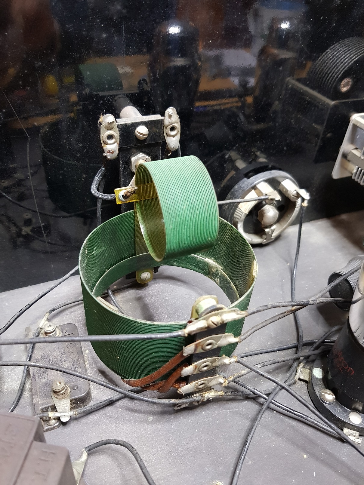
The vario-coupler has two coils were not connected but attached to separate circuits. So it functioned as an air-core RF transformer with variable coupling. The inner coil could be rotated from 0° to 90° angle with the outer, reducing the mutual inductance from maximum to near zero.
Detector
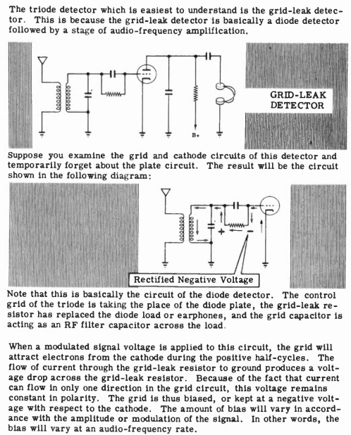
The radio use a grid leak detector.

a "grid leak" is the resistor placed in the grid circuit. The following article describes the operation of a grid leak detector
Audio Stages - Two
the Hammarlund Junior uses two Class A output stages, with a single valve driving the interstage audio transformer. 01A triodes were used in the early battery sets of the 1930s and early post-war period.
The interstage audio transformer provides; audio bandpass filtering, passive voltage amplification, and DC isolation.
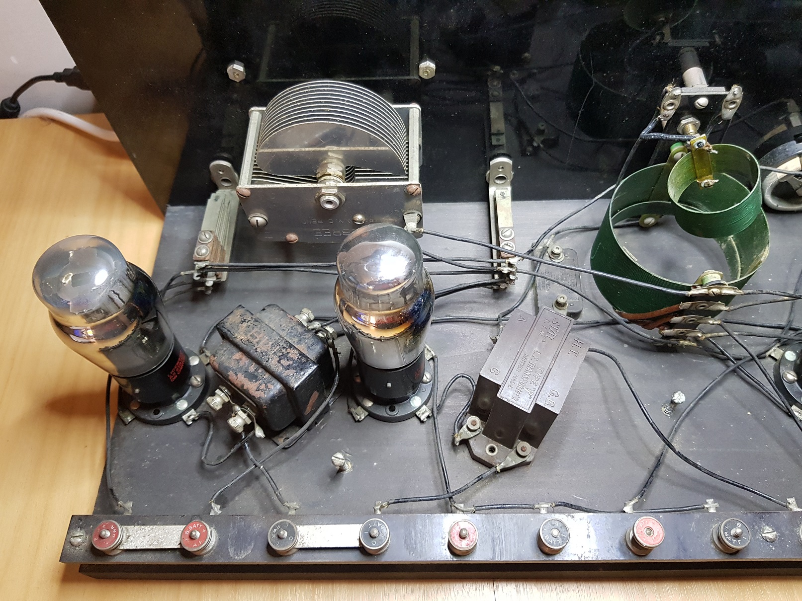
Output Stage Faults
A very common fault is a leaky grid coupling capacitor. This would cause the control grid to be at a potential above 0V, which alters the biasing of the valve causing it to draw excessive current. This problem is so common and familiar that Radiophile magazine and many restorers refer to it as "THAT Capacitor".

If the problem is ignored, it will get progressively worse until the valve fails, often destroying the output transformer in the process. It is interesting that the original documentation includes a transformer test

and that the one of the transformers appears to have been replaced from the original 1927 unit


Connections:
- PLATE = Anode
- HT = Power +B
- FIL = Grid Bias
- GRID = Grid
Ratio 3:1
Hooking it all up
Battery and Antenna connections from original documentation
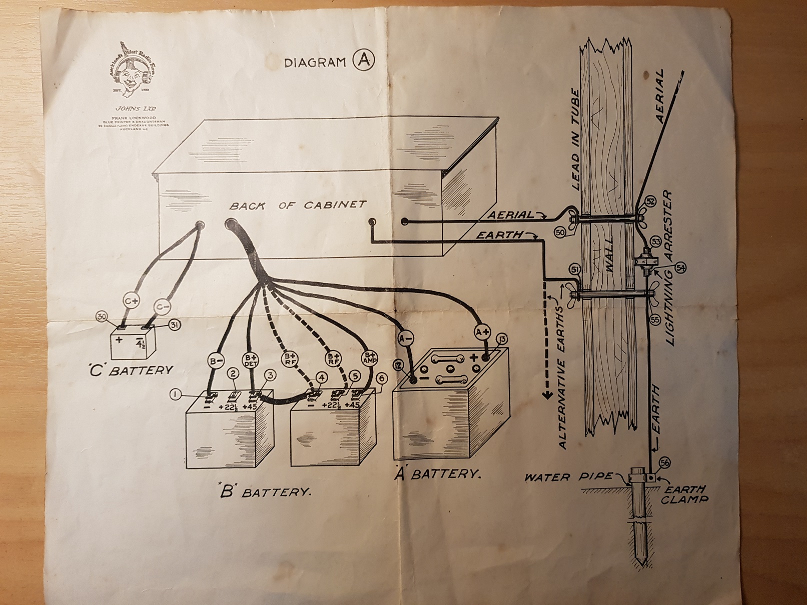
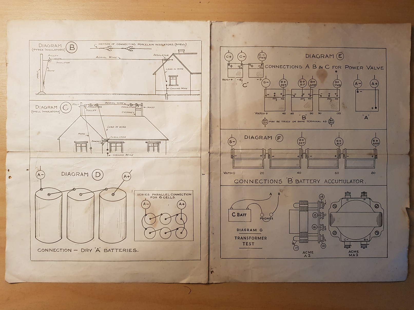
Audio
Baldwin Type C Mica Diaphragm Headset 1K3 Ohms DC
Link to Radio History
Link to Radio-a-Blast-from-The-Past-Wolff-Jacobson-1987-22-05-24.pdf